| View previous topic :: View next topic |
| Author |
Message |
RAPA
Joined: 17 May 2023
Posts: 31
Location: BCN Catalunya Spain
|
 Posted: Wed Sep 17, 2025 2:34 pm Post subject: Posted: Wed Sep 17, 2025 2:34 pm Post subject: |
 |
|
| murff wrote: | | I hope I'm not the only enthusiastic viewer.... |
You are not alone.
Thomasmanegiste, I hope your adventure ends successfully.
_________________
RP |
|
| Back to top |
|
 |
stenella
Joined: 03 Jun 2008
Posts: 48
Location: Antwerp, Belgium
|
| Posted: Sun Dec 28, 2025 10:31 pm Post subject: |
|
|
definitely watching  |
|
| Back to top |
|
|
Axel
Joined: 17 Jun 2024
Posts: 17
Location: France
|
| Posted: Mon Jan 12, 2026 12:01 pm Post subject: |
|
|
So many parts...[/quote]
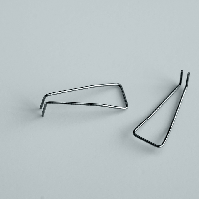
I recognize those ten carry springs ! I had to manufacture several to fix my 500713 type 2 😊 |
|
| Back to top |
|
|
thomasmanegiste
Joined: 03 Mar 2025
Posts: 9
Location: France
|
| Posted: Tue May 26, 2026 6:41 pm Post subject: |
|
|
Hello everyone,
Sorry for being offline for that long, I was way too busy these last months to be able to focus on that project (exams, work, urgent works...).
I juste realised I forgot to translate my last post on usinages.com, so here we go.
21st of december, 2025
I'm currently working on the gear sectors and sliding gears (10076 and 10053):
Sliding gears (10053):
https://drive.proton.me/urls/R3GF6RF928#MoZwe8rYuhBL
Up to this point, I tried to stick to the original design, machining the gear in sheet steel and mounting it onto a brass bushing. But this process causes some problems:
-It implies machining a 2.3mm bore, with a built-in key to ensure rotational linkage with the bushing. I tried to machine it using rotary broaching, obtaining mediocre results, but the process is not suited for semi-production, and I got a scrap rate of about 50%.
-When the previous step is successful, I then turn the 4.4mm diameter (head of teeth diameter), maintaining the part on a 2.3mm grooved arbor. Cutting forces often deform the part, or destroy the keyway by making the part turn onto the arbor.
https://drive.proton.me/urls/S463Q07P4M#WgN2UXE0LmkU
Picture above depicts the best result yet: we can see that the key is too small on the unmounted gear, the part moved when machining. I also tried to make a through bore, without key, soldering the gear onto the bushing.
I suppose that those gears were punched (seeing the statement "Stanzgrat entfernt", "remove punching burrs"), maybe prior to a remachining operation (I don't know if the tolerances are feasible by punching only. If anyone has experience with this technique, or a constructive opinion don't hesitate to share your view).
The most serious solution I found is to machine this assembly in a single part:
https://drive.proton.me/urls/91V7A1CMA0#drnmSwFmPKTS
https://drive.proton.me/urls/X6M5TYSFV0#M8bNW6RDaCoM
The profile of this part is turned out from bar stock, leaving enough material to hold it for milling. Then, I create the driving key by deforming the integrated bushing.
https://drive.proton.me/urls/GVX8W0G7E8#EBbFpFbDw0cO
https://drive.proton.me/urls/3046N2XNS4#2Hl0xWx8S4AR
Gear sectors and gear sectors holder (10001, 10213) :
https://drive.proton.me/urls/1P8C1Y0JKM#G35w9iPONFbR
I tried to find a solution to machine the gear sectors without slowly sinking into madness. I suppose that those were also punched, allowing to obtain the inner sharp corners.
https://drive.proton.me/urls/RYEV6P5KWW#4zYAADjVe0St
https://drive.proton.me/urls/QPKSP60NGG#HzwgZRdfAsyq
Current solution :
I'm using a two-pin design, allowing easy manufacturing and assembly. On usinages.com, I said that I didn't know if this was the final solution, but it seems to work quite well.
https://drive.proton.me/urls/Z78T07K90M#OD8opEVsk4Ln
https://drive.proton.me/urls/8W69CE3970#G1u3we3Jy8VL
That was the translation of the previous post. I will soon post the rest of the news, hopefully later this week.
Have a nice day! |
|
| Back to top |
|
|
thomasmanegiste
Joined: 03 Mar 2025
Posts: 9
Location: France
|
| Posted: Mon Jun 01, 2026 4:58 pm Post subject: |
|
|
Hello everyone,
Here is the rest of the work done since last update.
Since last time, I manufactured the grooved arbors (10014) with frontal gears (10052, assembly n°10216) for one whole Curta.
I started by grooving the arbors, that I turned a while ago. The groove is machined using a repurposed carbide form mill, mounted on a shop-made arbor.
https://drive.proton.me/urls/B58K48GDQ8#3QUC6sTLYveI
Positioning the part in the vise was a bit of a headache, the arbor being 2mm in diameter, and my parallels 8mm thick. I had to make an aluminium parallel, going under the arbor to true it.
Then, I machined the frontal gears. The most critical point was the conical bore. Those gears are pressed onto the arbor using a 4% conical bore. Considering the fact that I couldn't find a 4% conical reamer (or at outrageous cost), I started by single-point boring a few parts. The complexity of this operation is the tolerance of the bore : 2mm 0; -20µm at the entry point. I used this setup:
https://drive.proton.me/urls/0JKKXJ6CAG#brmeZwVgMc0M
https://drive.proton.me/urls/M3GNS5092C#byrYqoXhuqCV
The part is drilled at 1.5mm , then bored using a carbide micro-boring bar. I check the dimension of the bore using a split-ball bore probe. On the second picture, I'm near the lower limit of the tolerance (around 2,0195). I'm using the dial indicator, mounted on the back of the bench, to be able to reposition the tool. I'm making a few roughing cuts (0,05mm radius-wise), a semi-finishing pass (0,02mm radius-wise), followed by a measurement, and a finishing pass, corrected using the measured deviation.
This system works in theory, but it is quite complicated to use, and needs a fair bit of luck to work. A clumsy movement that hits the dial indicator at the back will throw off the readings, and the precision of this small machine is not adequate for this type of operation (slide's wear...). I chose to manufacture a D-bit conical reamer. The principle of those tools is to manufacture a cone, corresponding to the arbor's cone, ground on the top half to create the cutting face.
https://drive.proton.me/urls/XEVY4S08AG#3fLVXRlPVsI3
This tool works surprisingly well, with a better surface finish than the boring tool. The gears are then pressed onto the arbors.
Unfortunately, I didn't take any pictures of gear cutting operation. A picture at high magnification is visible in post #1, I will soon post pictures of the finished gears.
The idea is to offset the arbor by the base tooth radius, then to plunge using the Z axis and a conical frontal groove tool. I'm using a workholder with five grub screw, that index the arbor quickly, allowing me to machine the five teeth.
Last thing:
I started working on the cam holder (10009). I decided to modify this part to accommodate simpler cams : the original cams use an interrupted bore with an integrated key, that engages in one of the 3H9 grooves of the cam holder.
https://drive.proton.me/urls/HB7T8MY1VW#oX6xrlR9Mibg
https://drive.proton.me/urls/5G9VR8KY5G#zHouSs6Pcc7H
https://drive.proton.me/urls/WXA8VJ7EH4#t1v4Be2VHTvs
My current design uses pins, just like the gear sectors, the cams are positioned using two pins and screwed onto the cam holder. The spring used to lock addition or subtraction (10070 on the assembly drawing) mode will be shortened.
https://drive.proton.me/urls/98D7TYW6QC#Q59XuAALrGG1
https://drive.proton.me/urls/JS94NX590R#rzChiwUdz8gK
The rotational motion of the gear sectors holder (10001, lower part) will be transmitted to the cam holder using a pin. Since I removed the grooves on the cam holder, this pin will be mounted into the cam holder, and engaged in a groove machined into the sectors holder.
Now:
Small question to Curta owners and repairers.
In the Curta 1, we can find two types of five-toothed gears, sliding on the grooved arbors (parts n° 10038 and 10053). The only difference between these two is their thickness: 0,5mm for 10038 and 0,6mm for 10053.
https://drive.proton.me/urls/95MC7YFYRW#1kyY2u6OFdOQ
https://drive.proton.me/urls/BV5RBRN1K0#Pryl3n7R2BTy
Is it possible to minimise the number of parts needed by keeping only the thinnest one (10038), and modifying the thickness of the spacing rings of some assemblies? Having no Curta on hand to try, I can't estimate the consequences of this modification. |
|
| Back to top |
|
|
|
|
You cannot post new topics in this forum
You cannot reply to topics in this forum
You cannot edit your posts in this forum
You cannot delete your posts in this forum
You cannot vote in polls in this forum
|
Powered by phpBB © 2001, 2005 phpBB Group
|

